3D printing is becoming a large part of our business. Our customers are increasingly going 3D and we use it daily to build and repair scale models and to provide the service to our customers. We are a critical customer though and want to achieve what our skilled workers can do by hand. We have evaluated several FDM systems but this is just not for us as surface quality is ‘poor’ and complex support structures are needed. SLS prints are also not really what we looked for with rough surface and quite difficult to paint. Color prints where not even closely competing with our hand build models. For years now we have been using industrial jetting technology which we clean and paint in house. It provides fantastic models with very fine details but at a cost. But there was just nothing out there yet which could compete on detail AND build size. Maybe until now…
In April Formlabs introduced the Form 3 and Form 3L. A desktop SLA printer. I was familiar with Formlabs but the small build volume was never an option. The Form 3L however changes this. There is something else too, that caught my interest. Where as many others just try to improve existing SLA/DLP technology with all its flaws. Formlabs have thought outside the box and improved 2 key issues. 1) The adhesion forces of the print to the resin tank and 2) The fact that a central laser point becomes more and more oval the more you steer away from the center. It’s fantastic to see a company doing this.
Where as industrial SLA printers print straight up, Formlabs prints ‘up side down’. In industrial printing the model is standing up, resting on a plate that sinks into a large vat of resin. Each layer is build on top of the next and the part has very little stress other than gravity. On the downside you end up with a big machine. The laser need be above the vat, the vat always need be ‘full’. So you end up with a considerably larger and expensive machine. The vat contains many liters so swapping materials is quite an undertaking (and costly to fill).
Desktop printers however turns this process around. The model need to stick to the build plate which then moves up! On the bottom there is a see-through build vat which only has a small layer of resin. The laser works at the bottom of this vat. The model is build on the vat floor and each layer the part has to be pulled up and separated from the vat floor. This creates some stress on the part. Also having a very limited height between laser and vat floor made it almost impossible to create a larger build area due to the inaccuracies that occur when you angle the laser beam too much. The laser point becomes oval and the vat floor has an amount of reflection.
With the Form3, Formlabs much improved these key issues. The laser is now not stationary anymore but actually moves from left to right. Its build into a light processing unit. Inside this LPU the laser beam is still angled back to forward but due to an ingenious set of mirrors it will always hit the vat floor at a straight angle, thus having a perfect round point. So too summarise. The laser is moved to cover the y direction while the whole laser unit is moved to cover the x direction. The second advantage of this is that Formlabs now have a fully flexible vat floor. And only where the LPU is at that moment the vat floor is pushed up to the correct layer height so the laser can do its work. This reduced the peel forces considerably. The advantage is higher accuracy due to less stress on the part and less stress also mean smaller and less supports are needed.
After joining the Formlabs Roadshow and evaluating several of their parts we then ordered 6 of our own parts. These where all printed in standard grey resin and at 0.1mm layer heights.
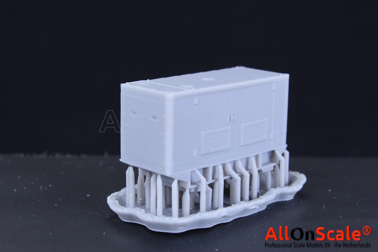
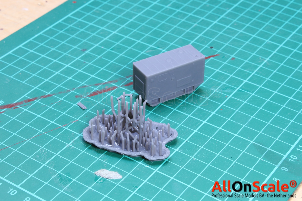
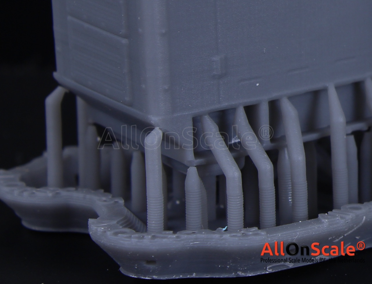
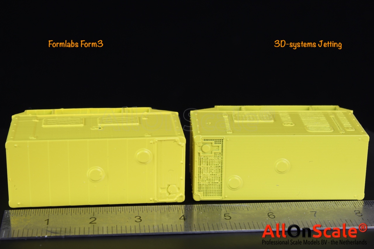
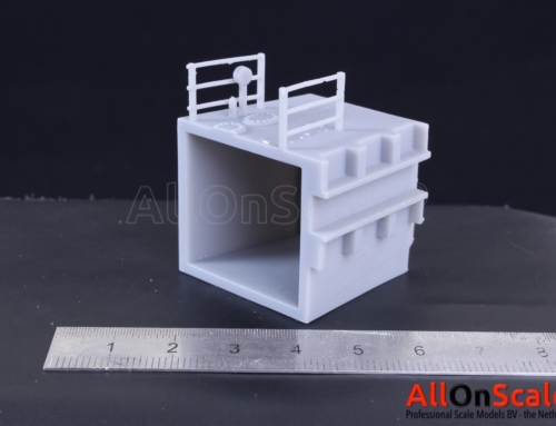
Our first object is a hydraulic power unit we used before. We can easily compare it to one from our jetting machine. First impression is great. On the zoomed in pictures the layer lines are still visible but looking at the part and feeling it its almost impossible to see and the surface looks and feels smooth. All the details stand out even some very small ones. The row of screws along the side actually only protrude 0.13mm in the model and all of them are visible in the print. Removing the support was easy. It feels very stiff at the beginning so felt a bit tricky to put some force on there with a delicate model but one by one they started popping off and quickly the whole support structure was removed without any damage to the model. minor dots are left on the model but for this test I just left them. I need to mention that Formlabs printed this model at a very low angle so layer lines are visible on top of the model. If the part was angled more the roof would also be smooth. There is some roundness of course, if compared with our industrial printer. Where the jetting machine delivers sharp corners the Formlabs corners are more smooth and rounded but this is at a microscopic level. One drawback of jetting is that it uses two fluids. One build fluid and one support fluid. Where they meet there is always a small amount of mixture of the two creating ‘fluffy’ not so smooth surface. We can strongly see this in our sample part. Where a protruding part in the model that needs support, create a whole stretch of surface below that show signs of ‘fluffiness’. This was always a annoying thing that needed to be sanded or counted with during the design. On the other hand we can see that the industrial machine has fantastic sharp detail especially in the gutters on the side and top. Ultra fine gutter is fully printed on the industrial machine but is fully closed on the Form3. The gutter holes are 0.2mm and the walls in between are 0.05. Amazing our jetting machine just builds this. And chapeau for Formlabs to coming this close at a fraction of the cost.
Part size vs CAD: Length 40.60mm (CAD 40.57), Width 16.58mm (CAD 16.42)
more to come…


