


Here is our second batch of Formlabs 3 sample parts.
First part is a ship winch. This time the part is angled correctly and printed with full support. It’s printed in standard resin grey and has 0.1 mm layer heights. Its quite an amazing little part that was drawn long time ago when we where just starting with 3D-printing. It’s got some fine detail and thin structures. The edges of the which goes down to 0.5mm. The legs and other parts are also down to 0.5mm. They where printed nicely but unfortunately the two unsupported legs came of together with the support structure. We still need gain a lot of experience with supports.
Second part is a part of an offshore unit we made lately. Its also super nicely printed. In the close up images above you see the print lines but holding the part in your hand all surfaces feel and look smooth. Detail is great. Compared to our industrial multi-jet printer the differences are really very minor. There is a clamp and the bottom with only 0.5mm spacing in-between and this is fused together on the Form3 while actually open on the MJP. The screws also become more round dots while on the MJP you can see they have 6 sides. Bolt diameter is ø1mm. On the T-end there was a tiny gutter which is now barely visible. Again with a 0.075 gutter dept its amazing its still visible. The 0.025mm resolution and 0.085mm laser helps. The individual holes of the gutter are visible on MJP but not on the Form3. Hole diameter ø0.2. Gutter thickness between holes 0.045 🙂 This part should also have been printed without the internal supports. They are a pain. What I don’t like and need look into are some very small supports that are placed under the screws. They are fused together with the model and didn’t seem to be necessary.
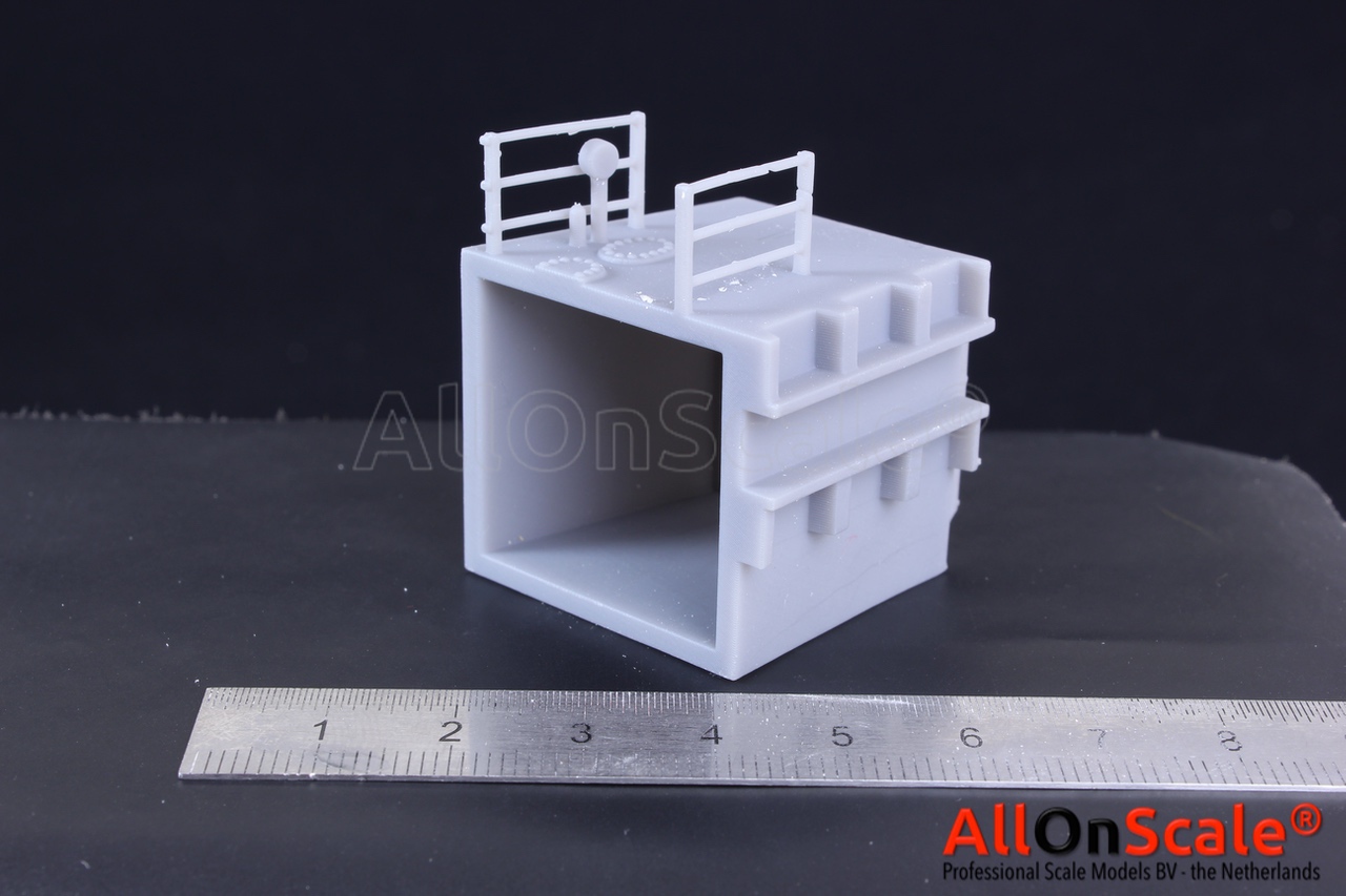
Last but not least we have a part of a dredger hull. We regularly print parts with has railings mounted on them directly. So I needed a try. Railing pole is 0.8x1mm and the railings itself are round 0.75mm. This part was rotated and placed correctly. Its very smooth and nice and has fairly sharp corners. Details came out nice and so did the railing. Even the square poles and round railings came out nice. Both also very straight. There is a small xy shift on the upper railing. Not sure why that happend. Dimension wise we are pretty good but there is also a differences depending on orientation I guess. The width of the printed part is 31.26mm (CAD 31.29mm)and the height is 29.83mm (CAD 29.70mm). Width of the sliding rail 6.38mm (CAD 6.67). So width and height are very good <0.1% but then the gap has a 4% difference. We also designed it with a 0.1mm gap to slide into another part but this was not enough. Seems we need a bit more gap especially in the corners.
Enjoy!